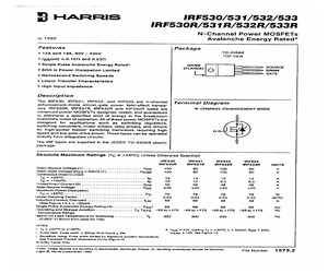
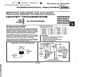
0V TOP VIEW * rps(on) = 0.162 and 0.239 * Single Pulse Avalanche Energy Rated* DRAIN SOURCE (FLANGE) * SOA is Power-Dissipation Limited O oe * Nanosecond Switching Speeds Linear Transfer Characteristics High Input Impedance Description The IRF530, IRF531, IRF532, and IRF533 are n-channel enhancement-mode silicon-gate power field-effect transis- tors. IRF530R, IRF531R, IRF532R and IRF533R types are advanced power MOSFETs designed, tested, and guaranteed Terminal Diagram N-CHANNEL ENHANCEMENT MODE to withstand a specified level of energy in the breakdown D avalanche mode of operation. All of these power MOSFETs are designed for applications such as switching regulators, switching converters, motor drivers, relay drivers, and drivers for high-power bipolar switching transistors requiring high G speed and low gate-drive power. These types can be operated directly from integrated circuits. The IRF types are supplied in the JEDEC TO-220AB plastic s package. Absolute Maximum Ratings (Tc = +
 5 Pages, 250 KB, Scan
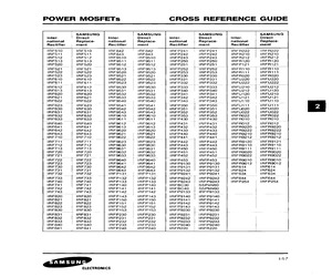
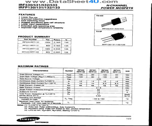
IRF532, IRF533, RF1S530, RF1S530SM 12A and 14A, 80V and 100V, 0.16 and 0.23 Ohm, July 1998 N-Channel Power MOSFETs Features * 12A and 14A, 80V and 100V * FDS(ON) = 9.16Q and 0.230 * Single Pulse Avalanche Energy Rated * SOA is Power Dissipation Limited * Nanosecond Switching Speeds Linear Transfer Characteristics * High Input Impedance * Related Literature - TB334 Guidelines for Soldering Surface Mount Components to PC Boards Description These are N-Channel enhancement mode silicon gate power field effect transistors. They are advanced power MOSFETs designed, tested, and guaranteed to withstand a specified level of energy in the breakdown avalanche mode of operation. All of these power MOSFETs are designed for applications such as switching regulators, switching conver- tors, motor drivers, relay drivers, and drivers for high power bipolar switching transistors requiring high speed and low gate drive power. These types can be operated directly from integrated circuits. Formerly developmental type
 7 Pages, 397 KB, Scan
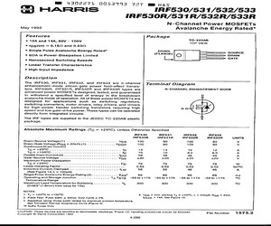
 * rps(on) = 0.162 and 0.230 i te Single Pulse Avalanche Energy Rated DRAIN SOURCE | BS (FLANGE) SOA is Power-Dissipation Limited Oo eae * Nanosecond Switching Speeds * Linear Transfer Characteristics * High Input Impedance Description The IRF530, IRFSS1, IRF532, and IRFS33 are n-channel Terminal Diagram enhancement-mode silicon-gate power field-effect transis- tors. IRFS30R, IRF531R, IRF532R and IRF533R types are N-CHANNEL ENHANCEMENT MODE advanced power MOSFETs designed, tested, and guaranteed to withstand a specified level of energy in the breakdown D avalanche mode of operation. All of these power MOSFETs are designed for applications such as switching regulators, switching converters, motor drivers, relay drivers, and drivers for high-power bipolar switching transistors requiring high G speed and low gate-drive power. These types can be operated directly from integrated circuits. The IRF types are supplied in the JEDEC TO-220AB plastic $s package. Absolute Maximum Ratings (Tc =
 5 Pages, 390 KB, Scan
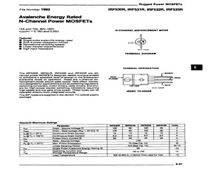
 Power MOSFETs 12A and 14A, 60V~100V fps(on) = 0.18Q and 0.25Q Features: @ Single pulse avalanche energy rated @ SOA is power-dissipation limited @ Nanosecond switching speeds @ Linear transfer characteristics @ High input impedance The IRF530R, IRF531AR, IRF532R and IRF533R are ad- vanced power MOSFETs designed, tested, and guaranteed to withstand a specified level of energy in the breakdown avalanche mode of operation. These are n-channel en- hancement-mode silicon-gate power field-effect transis- tors designed for applications such as switching regulators, switching converters, motor drivers, relay drivers, and driv- ers for high-power bipolar switching transistors requiring high speed and low gate-drive power. These types can be operated directly from integrated circuits. The IRF-types are supplied in the JEDEC TO-220AE plastic package. Absolute Maximum Ratings IRF530R, IRF531R, IRF532R, IRF533R N-CHANNEL ENHANCEMENT MODE Oo 920S-42658 TERMINAL DIAGRAM TERMINAL DESIGNATION ~ SOUR
 5 Pages, 188 KB, Scan
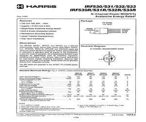
100V owe * rpsg(on) = 0.162 and 0.230 * Single Pulse Avalanche Energy Rated* (FLANGE) __ SOURCE SOA is Power-Dissipation Limited L. oO _= OeE. Nanosecond Switching Speeds Linear Transfer Characteristics High Input impedance Description The IRF530, IRF531, IRF532, and IRF533 are n-channel enhancement-mode silicon-gate power field-effect transis- tors. IRF530R, IRF531R, IRF532R and IRF533R types are advanced power MOSFETs designed, tested, and guaranteed Terminal Diagram N-CHANNEL ENHANCEMENT MODE to withstand a specified level of energy in the breakdown o avalanche mode of operation. All of these power MOSFETs are designed for applications such as switching regulators, switching converters, motor drivers, relay drivers, and drivers for high-power bipolar switching transistors requiring high G speed and low gate-drive power. These types can be operated directly from integrated circuits. The IRF types are supplied in the JEDEC TO-220AB plastic s package. Absolute Maximum Ratings (Tc = +
 5 Pages, 195 KB, Scan
 IRF641 SGsP477_ | 553 IRF530FI__ | IRFS30FI 291 | IRF642 SGsP477_| 553 IRF530P _| IRFS30F I 291 | IRF643 sqspa77 | 553 IRF531 IRF531 291 | IRF720 IRF720 307 IRF531FI | IRF531FI 291 | IRF720FI | IRF720FI 307 IRF531P | IRFS31FI 291 | IRF720P | IRF720F| 307 IRF532 IRF532 291 | IRF721 IRF 721 307 IRF532F1 | IRF532F I 991 | IRF721eI | IRF721FI 307 IRF532P | IRF532F I 291 | IRF721P | IRF721F I 307 IRF533 IRF533 291 | IRF722 IRF722 307 IRF533F1 | IRF533F 291 | IRF722F1 | IRF722FI 307 IRF533P | IRFS33FI 291 | IRF722P | IRF722FI 307 IRF540 IRF540 295 | IRF723 IRF723 307 IRF540FI | IRFS40F I 295 | IRF723FI | IRF723FI 307 IRF540P _| IRF540F I 295 | IRF723P (| IRF723FI 307 IRF541 IRF541 295 | IRF730 IRF730 313 * Datasheet available on request. 28 i SGS-THOMSON IF, iachoerecrnamicsCROSS REFERENCE INDUSTRY SGS-THOMSON INDUSTRY GS-THOMSON STANDARD | SGSTHOMSON | Neapecy | PAGE 7 cranpann | SGS-THOMSON | Neanesy | PAGE IRF730FI | IRF730F1 313 | IR
 6 Pages, 262 KB, Scan
D 2SC2503 BUW12A 2SC1308K 2SD1497 2SD1497 2SD1455 2SD1497 KAA11806 BU806 2SD903 2SD871 ECG238 2SC2502 BU407 2SC2502 BU406 2SD1069 2SC2504 ECG2310 2SD822 ECG2300 ECG2300 2SD811 ECG238 433-2 BU508A ECG2315 KAA11508 2SD1175 2SD1016 BU705 ECG89 BU3702F BUA10A IRF532 BUS13 BUS23C BUV46 BUV47 GM3044 BUZ71A ECG66 BUY69B BUW46 2SC2335 BUV47A RCA9212A IRF533 BUX48A MJ13335 BUV48A ECG2311 BUV47A BUV48 BUV48A BUV48B BUW12 BUW12A BUW48 BUX32B 2SD822 BUX48 BUX80 BUX81 BUY69B BUY71 BUY89 BUZ10 BUZ10A BUZ10B BUZ11A BUZ14A BUZ14B BUZ17 BUZ18 BUZ20 BUZ20A BUZ20B BUZ21 BUZ23 BUZ23A BUZ23B BUZ24 BUZ24B BUZ25 BUZ28 BUZ31 BUZ32 BUZ32A BUZ32C BUZ34 BUZ35 BUZ35A BUZ36 BUZ38 BUZ41 BUZ41A BUZ41B BUZ42 BUZ42A BUZ42B BUZ44 BUZ44A BUZ44B BUZ45 BUZ45C BUV48A BUV48A BUV48C 2SC3090 2SD811 2SC2751 BU208A BUY69B BUX48 BUX48A 2SD621N BUY69A IRF541 IRF543 IRF533 IRF543 IRF151 IRF153 IRF153 IRF151 IRF530 IRF532 IRF520 IRF540 IRF130 IRF130 IRF150 IRF152 IRF140 IRFP141 IRF640 IRF630 IRF631 IRF633 IRF240 IRF230 IRF231 IRF
 314 Pages, 275 KB, Original
IRF242 IRF243 2-98 2-98 2-98 2-98 IRF520 IRF521 IFR522 IRF523 2-67 2-67 2-67 2-67 IRF820 IRF821 IFR822 IRF823 2-127 2-127 2-127 2-127 FRP1605 FRP1605CC FRP1610 FRP1610CC 2-55 2-59 2-55 2-59 IRF250 IRF251 IRF252 IRF253 2-103 2-103 2-103 2-103 IRF530 IRF531 IRF532 IRF533 2-72 2-72 2-72 2-72 IRF830 IRF831 IRF832 IRF833 2-132 2-132 2-132 2-132 FRP1615 FRP1615CC FRP1620 FRP1620CC 2-55 2-59 2-55 2-59 IRF320 IRF321 IRF322 IRF323 2-107 2-107 2-107 2-107 IRF540 IRF541 IRF542 IRF543 2-78 2-78 2-78 2-78 IRF840 IRF841 IRF842 IRF843 2-138 2-138 2-138 2-138 FRP2005CC FRP2010CC FRP2015CC FRP2020CC 2-51 2-51 2-51 2-51 IRF330 IRF331 IRF332 IRF333 2-112 2-112 2-112 2-112 IRF610 IRF611 IRF612 IRF613 2-152 2-152 2-152 2-152 IRFC110 IRFC120 IRFC130 IRFC140 3-6 3-6 3-6 3-6 * Alpha-Numeric Index Power MOSFETs and Ultra-Fast Recovery Rectifiers Fairchild Part Number Page Number Fairchild Part Number Page Number Fairchild Part Number Page Number Fairchild Part Number Page Number IRFC150 IRFC210 IRFC220 IRFC230 3-6 3-6 3-
 243 Pages, 63820 KB, Original
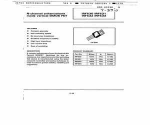
IRF532 IRF533 FEATURES Compact geometry Fast switching speeds No secondary breakdown Excellent temperature stability High input impedance Low current drive Ease of paralleling DESCRIPTION PRODUCT SUMMARY A compact cell geometry forms the basis of this Ferranti MOSFET. Optimised for low on- resistance, low capacitance and fast switching IRF530 100V 148 0.182 this device is manufactured using the latest IRF531 60V 14A 0.182 computer controlled processing techniques in IRF532 100V 128 0.250 order to achieve greater stability, rellability and ruggedness. Part No. BVoss Ib Rosien) IRF533 60V 12A 0.252 G-58ZE TB a ZETEX SEMICONDUCTORS 45D D mm 9970574 go05557 3 7 | a 95D 05557. OD IRF530 IRF531 IRF532 IRF533_=CO; ABSOLUTE MAXIMUM RATINGS T. 3 G . / | i Parameter IRF530 | IRF531 | (RF532 | IRF533 | Units : Vos Drain-source voltage 100 60 100 60 Vv Ip Continuous drain current (@ Te=25C) 14 14 12 12 A lpm Pulse drain current 56 56 48 48 A , Ves Gate-source voltage +20 +20 +20 +20
 11 Pages, 494 KB, Scan
636 IRFP440 2SK626 | (RFP151 2SK633 IRFP252 2SK637 IRFP452 iL SAMSUNG SAMSUNG SAMSUNG SAMSUNG Direct Re- Direct Re- Direct Re- Direct Re- MOTOROLA | placement | MOTOROLA | placement | MOTOROLA | placement | MOTOROLA | placement MTH6N55 SSH6N55_ | MTP10N08 IRF532 MTP2N50 IRF822 MTPSN40 IRF730 MTH6N60 SSH6N60 | MTP10N10 {RF532 MTP3N12 IRF623 MTP7N12 IRF633 MTH8N55 SSH8N55 | MTP10N12 IRF643 MTP3N15 IRF623 MTP7N15 IRF633 MTH8N60 SSH8N60 | MTP10N25 IRF743 MTP3N18 IRF622 MTP7N18 IRF632 MTH7N35 IRFP343 MTP12N05 IRF533 MTP3N20 IRF620 MTP7N20 IRF632 MTH7N40 IRFP342 MTP1N45 IRF823 MTP3N35 | {RF721 MTP15N15 IRF643 MTH8N35 IRFP343 MTP1N50 IRF822 MTP3N40 | IRF720 MTP20N08 IRF542 MTH8N40 IRFP342 MTP2N18 IRF612 MTP3N55 | SSP4N55_ | MTP20N20 IRF542 MTH15N18 IRFP242 MTP2N20 IRF612 MTP3N60 SSP4N60_ | MTP20N05 IRF541 MTH15N20 IRFP242 MTP2N25 IRF723 MTP4NO08 IRF510 MTP25N06 IRF541 MTH20N12 IRFP253 MTP12N06 IRF533 MTP4N10 IRF510 MTD10NO05A _ | IRFRO20 MTH20N15 IRFP253 MTP12N08 IRF532 MTP4N12 IRF623 MTD4P
 4 Pages, 207 KB, Scan
advanced line of power MOSFET transistors. IRF530_ 100V 0.160 14A The efficient geometry and unique processing of this latest State of the Art design achieves: very low on-state IRF531 80V 0.168 14A resistance combined with high transconductance; superior IRF532_ 100V 0.230 12A reverse energy and diode recovery dv/dt capability. IRF533 | = 80V 0.239 12A The HEXFET transistors also feature all of the well established advantages of MOSFETs such as voltage FEATURES: control, very fast switching, ease of paralleling and . temperature stability of the electrical parameters. Repetitive Avalanche Ratings @ Dynamic dv/dt Rating They are well suited for applications such as switching : : ' power supplies, motor controls, inverters, choppers, audio m Simple Drive Requirements amplifiers and high energy pulse circuits. M@ Ease of Paralleling CASE STYLE AND DIMENSIONS Hn L- 13200650 10.54 (0.415) . : TERM 3 ~ SOURCE MAX. TEAM 2 - DRAIN TEAM 1 ~ GATE >t 1.15 (045) MIN. ssn | 432 (0.170) 15.09 (0.594) MAX. 2.7
 8 Pages, 552 KB, Scan
ucture Lower input capacitance Extended safe operating area Improved high temperature reliability IRF530/531/532/533 TO-3P PRODUCT SUMMARY Part Number | Vos__| Rosion 'b IRFS30/IRFP130 100V | 0.160 14A IRFP 130/131/132/133 | IRFS31/IRFP131 80V | 0.169 14A IRF532ARFP 132 100V | 0.232 12A [ IRF533/IRFP133 sov | 0.230] 124 MAXIMUM RATINGS Characteristics Symbol IRF 130 RFP IS! IEP 132 IRFP193 | Unit Drain-Source Voltage (1) Voss 100 80 100 80 Vdc Drain-Gate Voltage (Rag=1.0MQ)(1) Vocr 100 80 100 80 Vde Gate-Source Voltage Vas +20 Vde Continuous Drain Current Te =25C Ip 14 14 12 12 Adc Continuous Drain Current Tc=100C lp 10 10 8.3 8.3 Adc Orain CurrentPulsed (3) , lom 56 56 48 48 Adc Gate CurrentPulsed lom +1.6 Adc Single Pulsed Avalanche Energy (4) Eas 69 mJ Avalanche Current las 14 A Total Power Dissipation @ Tc=25C Po 77 Watts Derate above 25C 0.62 w/c eo Tu Ta ~85 0150 c Maximum Lead Temp. for Soldering Th 300 C Purposes, 1/8" from case for 5 seconds Notes: (1) Ty=25C to 150C (2) Pulse test: Puls
 6 Pages, 370 KB, Scan
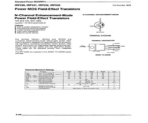
IRF532, IRF533 File Number 1575 Power MOS Field-Effect Transistors N-Channel Enhancement-Mode Power Field-Effect Transistors 12A and 14A, 60V-100V fos(On) = 0.18 Q and 0.250 Features: @ SOA is power-dissipation limited @ Nanosecond switching speeds @ Linear transfer characteristics B High input impedance @ Majority carrier device The IRF530, IRF531, IRF532 and IRF533 are n-channel enhancement-mode silicon-gate power field- effect transistors designed for applications such as switch- N-CHANNEL ENHANCEMENT MODE s 92CS-33741 TERMINAL DIAGRAM TERMINAL DESIGNATION ing regulators, switching converters, motor drivers, relay SOURCE drivers, and drivers for high-power bipolar switching tran- DRAIN |, sistors requiring high speed and low gate-drive power. (FLANGE) @ }h, - DRAIN These types can be operated directly from integrated __ circuits. _}-F a: . TOP VIEW GATE The IRF-types are supplied in the JEDEC TO-220AB plastic o2cs-39520 package. JEDEC TO-220AB Absolute Maximum Ratings Parameter IR
 5 Pages, 170 KB, Scan
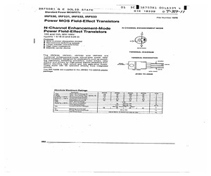
IRF532, IRF533 File Number 1575 Power MOS Field-Effect Transistors N-CHANNEL ENHANCEMENT MODE N-Channel Enhancement-Mode Power Field-Effect Transistors 0 12A and 14A, 60V-100V" fps(On) = 0.18. Q and 0.250 Features: . | 8 SOA is power-dissipation limited " Nanosecond switching speeds @ Linear transfer characteristics @ High input impedance @ Majority carrier device 3 9208-33741 TERMINAL DIAGRAM The IRF530, IRF531, IRF532 and !tRF533 are n-channel enhancement-mode silicon-gate power field- TERMINAL DESIGNATION effect transistors designed for applications such as switch- ing regulators, switching converters, motor drivers, relay SOURCE drivers, and drivers for high-power bipolar switching tran- prat jf sistors requiring high speed and low gate-drive power. (FUANGE) O a These types can be operated directly from integrated __ circuits. * = TOP VIEW GATE The IRF-types are supplied in the JEDEC TO-220AB plastic g2cs-s05z8 package. JEDEC TO-220AB Absolute Maximum Ratings Parameter IAF530 (RF
 5 Pages, 163 KB, Scan


