ated Product Folder Links: UCC28630 UCC28631 UCC28632 UCC28633 UCC28634 UCC28630, UCC28631 UCC28632, UCC28633, UCC28634 www.ti.com SLUSBW3D - MARCH 2014 - REVISED DECEMBER 2017 5 Device Comparison Table FEATURES ACTIVE-X CAPACITOR DISCHARGE OVERLOAD TIMER UCC28630D Yes UCC28631D No UCC28632D ORDER NUMBER ADJUSTABLE CC LIMIT FREQUENCY DITHER SECONDARYSIDE WAKE UP Yes No Yes SD Pin No Yes Yes SD Pin No No Yes No SD Pin UCC28633D Yes No Yes Yes VSENSE Pin UCC28634D No No Yes Yes SD Pin 6 Pin Configuration and Functions 7-Pin SOIC Package D (Top View) VSENSE 1 8 HV SD 2 CS 3 6 VDD GND 4 5 DRV PIN Functions PIN NAME NO. I/O DESCRIPTION CS 3 I Current sense input DRV 5 O Output drive pin for the external flyback MOSFET GND 4 G Ground reference connection for all signals HV 8 P High-voltage connection to the internal high-voltage start-up current source SD 2 I Latching fault shutdown input pin. May be connected to an external temperature sensor VDD 6 P Bias supply input pin to the device. Decoupled with
 86 Pages, 3978 KB, Original
CA DRV 100k R3 D2 1N4007 1000V 4 5 6 8 - 2 ~ ~ + Copyright (c) 2014-2015, Texas Instruments Incorporated NT1 Net-Tie -VPRI 1 CS SD 4 3 2 1 STARPT GND RLTI-1098 C7 27F 1 L2 47.7H 3 C6 120pF C15 10pF R5 1.00k 0 R6 DANGER HIGH VOLTAGE GND TP5 BR1 800V VSENSE UCC28630D DRV VDD HV U1 D3 1N4007 1000V 3 LINE TP1 -VPRI t SLUUAX9B - February 2014 - Revised April 2015 Submit Documentation Feedback C5 100F RT1 470k of net 100 R4 STARPT R8 39k DRV R9 180k C8 0805 R12 1206 R7 22.6k MAG Minimize copper area -VPRI VDC HV TP6 R11 47.0 STARPT 0 R20 D4 BAV70-V R10 3.90k 100V D5 D6 C16 10pF 4.7 R13 MAG R15 100k 1 +VSW MURS160-13-F CS D9 1SMB5949BT3G 100V D8 1SMB5947BT3G 82V 2 2 6 1 5 4 R16 0.2 11 10 9 8 also High voltage Net of VSW net Minimize copper area RLTI-1100 T1 TP7 GND Q1 STF13NM60ND 600V -VPRI -VPRI 3 C10 0603 R17 1206 NTST30100CTG 100V D7 C9 2200pF -VPRI Connect 2 pins of bobbin to Vsec and Ret nets VSEC RET C11 680F R18 8.20k LED1 Green TP8 TP9 RET TP10 +VOUT C13 1F +VOUT +VOUT 1 C12 680F J2 OUTPUT R/A S
 28 Pages, 1219 KB, Original
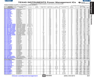
 4 4 4 4 4 4 4 70 99 99 99 99 99 100 100 100 50 50 50 85 100 100 100 100 100 100 100 100 120 80 80 80 83 100 100 100 1000 1000 1000 1000 1000 500 500 1000 1000 1000 1000 1000 1000 1.5 35 35 38 35 35 35 35 72 0.015 0.015 0.015 0.015 20 20 17 17 17 20 20 20 UCC28630D UCC28720D UCC28740D UCC28722DBVT UCC28730D UCC28713D UCC28710D UCC28711D UCC28250RGPT UC3825DW UC3825ADW UC3825AN UC3825N UC3879N UC2879DW UCC2895DW UCC2895N UCC3895DW UC2875N UC3875DWP UC3875N mouser.com/tipowermanagement Frequency Input UVLO Thresholds (Max.) (kHz) Voltage (Max.) On/Off (V) Error Amplifier 1 8.4/7.6 8.4/7.6 8.4/7.6 8.4/7.6 8.4/7.6 16/10 16/10 16/10 16/10 16/10 16/10 8.4/7.6 16/10 4.1/3.6 9.4/7.4 9.4/7.4 12.5/8.3 12.5/8.3 12.5/8.3 8.4/7.6 14.5/9 7.5/12.5 2.44/2.56 5.3/6.7 5.3/6.7 7.25/12.5 5.3/6.7 1.5/0.75/4.25 1.5/1.5/2.44/2.56 2.44/2.56 1.3/2.95 0.45/0.55 1.5/0.4/1.25 0.4/1.20 16/10 8.4/7.6 8.4/7.6 8.4/7.6 8.4/7.6 8.4/7.6 8.4/7.6 8.4/7.6 8.4/7.6 16/10 16/10 16/10 8.4/7.6 4.1/3.6 7.2/6.9 12.5/8.3 7/6.6 8.4/7.6 8.4/7.
 1 Pages, 230 KB, Original


